
Procedurally generated meshes have several uses in game development:
- You can use them for crisp, non-standard UI components.
- You can use them to render lines that look correct if your engine (in this case, Unity) cannot.
- You can make intricate mathematical objects that may be difficult to do by hand.
- You can use them to create worlds, creatures, and props.
Making a mesh is not always the right solution, but in Unity, it is surprisingly easy, and in this post I describe the basics.
Related Posts
To make a custom mesh, you need at the very least two things: where the vertices of the mesh are, and how the mesh is triangulated, that is, which vertices make up each triangle of the mesh.
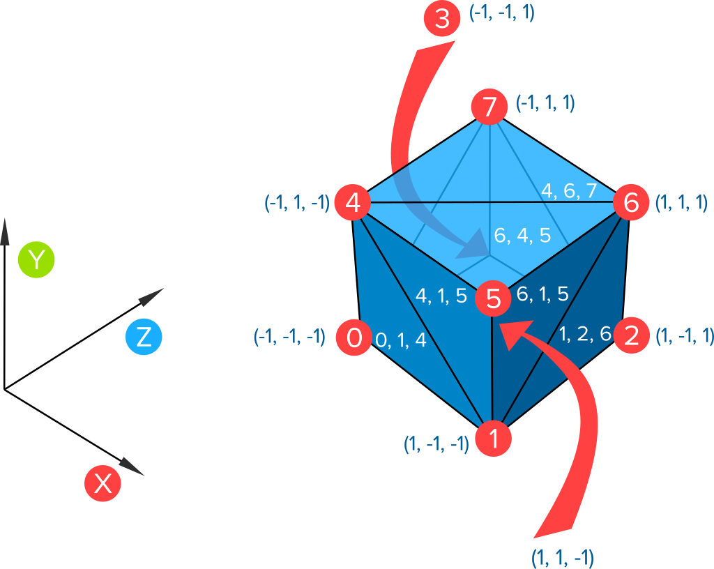
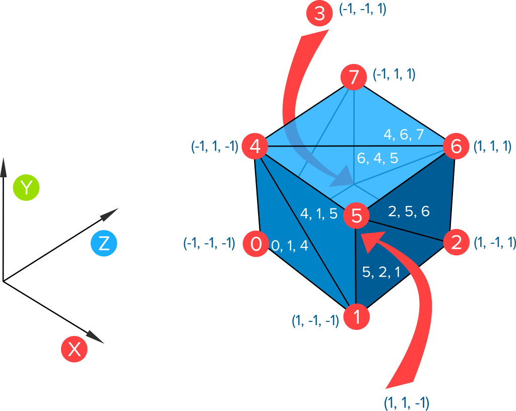
The images above show two meshes of a cube with the same vertices, but different triangulations. I also assigned a unique index to each vertex. This makes it possible to say things like “vertex 3” and “there is a triangle made from vertices 0, 1, and 2”. Triangulations are given in terms of vertex indices, not the vertices themselves. This is not only more compact, but sometimes different vertices appear in the same position, so using indices avoid any ambiguity.
For meshes created programmatically, you usually have an algorithm (possibly a formula) for these two things. Although you can certainly simply list the vertices and the triangulation directly, for meshes like that it is usually easier to simply use a modeling tool (that is what they are for). As we will see, the ability to simply list the two things we need can be a valuable debugging aid.
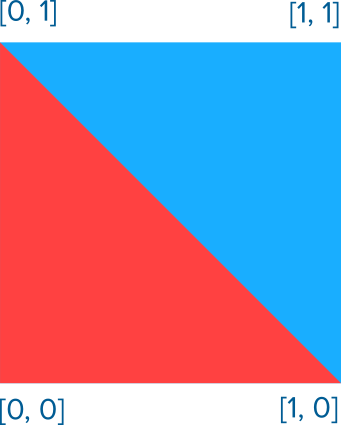
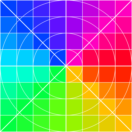
If you want a textured mesh, you also need to calculate UVs. UVs are normalized 2D coordinates that map into a texture. Each triangle in the mesh has a corresponding triangle in the texture. For example, if vertex 0, 1 and 2 have texture coordinates [0, 0], [1, 0], [0, 1], then the triangle 0, 1, 2 will be textured red if the texture looks like the blue and red square below.
Before looking at detailed calculations, let’s look at the general structure of a mesh generator in Unity. We will use this as the base for all our builders.
var mesh = new Mesh();

var vertices = CalculateVertices();
mesh.SetVertices(vertices);

var triangles = CalculateTriangles();
mesh.SetTriangles(triangles, 0);

var uvs = CalculateUvs(vertices);
mesh.SetUVs(0, uvs);

mesh.RecalculateBounds();
mesh.RecalculateNormals();
meshFilter.sharedMesh = mesh;
The full implementation has a lot of detail, and is shown at the end of the post. It is implemented as a component. You will need a MeshFilter component, and to be able to see the mesh, you will also need a MeshRenderer.
The basic operations are very simple though; we calculate what we need, then we put it together in a few lines.
The real work comes in to calculate the vertices and triangles. I do this work away from the computer (usually long before writing any code), as I find it’s easier to focus on the math and not deal with implementation complexities yet. Here are the basic steps:
- Assign an index to each vertex.
- Find an algorithm for calculating vertices. This is often a formula or set of formulas in terms of the vertex index.
- *Calculate how many vertices there are.
- Find an algorithm for calculating the vertex indices for each triangle. This too is often a formula or set of formulas in terms of the vertex index.
- *Calculate how many vertices there are.
- If necessary, calculate normals. Check that you have the same number as vertices. (This is not explained in this post).
- If necessary, calculate UVs. Check that you have the same number as vertices.
You have a lot of freedom in how you organize the data; the machine will not care. (Some schemes may be a bit slower, but if you need to optimize, a working reference implementation will be valuable in programming the more complicated optimized version). Therefore, always choose a system that will make the math easier. Often, the first triangle will have the first vertex, and the last triangle to have the last vertex.
Always choose a scheme with the simplest math.
The two steps marked with an * are checks to help avoid making certain errors (I make them very consistently if I skip these steps).
Finding formulas for shapes is of course a very broad problem, but I assume that you already understand your shape in some mathematical way (the reason why you are creating it dynamically in the first place). I will look at just one simple example and a variation in this post.
Example
Circular Sector
This mesh will be to approximate a circular sector in the XY plane with center at the origin and radius one (the shape between two radiuses and the circumference of a circle) which starts at angle 0, and ends at a given angle, using triangleCount triangles.
Assign vertex indices: There are two types of vertices; the center vertex, and perimeter vertices. There are four schemes that seem “natural”, depending on
- whether we make the first or last vertex the center, and
- whether we make the perimeter vertices go clockwise or anticlockwise.
For the first decision, it seems there is a slight advantage if we make the center vertex last (allowing our loop counter to match vertex indices). However, we will see that we often have some offset for a list of things, and the optimization suggested here does not generalize. Therefore, it pays to get used to that format; therefore we will put the center vertex first.
The last choice is easier to make, we follow the same order as Unity angles, so we go anti-clockwise.
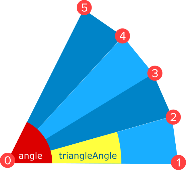
Calculate the vertices: If the angle of the sector is angle, then the inner angle of each triangle is triangleAngle = angle / triangleCount. The center vertex is at the origin, vertices[0] = [0, 0, 0], and the other vertices are given by vertices[i + 1] = [cos(i * triangleAngle), sin(i * triangleAngle), 0], where i goes from 0 to triangleCount.
Note that this formula is simple because of specific choices in the problem:
- The circle is at the origin (so no positional offsets are necessary).
- We start at angle 0 (therefore no nasty angle offsets need to be calculated).
- The radius is 1 (therefore there is no scaling factor).
- We are in the XY plane (therefore we don’t have to do any tricky transformations or have to deduce a more difficult formula ourselves).
These choices were made on purpose. If we need a translated, scaled or rotated version, but do that in the Unity editor. There is no need to add error-prone or tricky math if it can be avoided.
Calculate the number of vertices: Indices go from 0 to triangleCount + 1, so there are triangleCount + 2 (there are triangleCount + 1 perimeter vertices, and the center vertex).
Calculate the triangles: Each triangle is made from vertex 0, i + 1 and i + 2, where i ranges from 0 to triangleCount - 1. (Check: last triangle is made from 0, triangleCount - 1 + 1, and triangleCount - 1 + 2 equivalent to 0, triangleCount, triangleCount + 1, consistent with the fact that we have triangleCount + 2 vertices, going from 0 to n + 1.
Calculate the number of triangles: There are triangleCount triangles by design, but we check whether our previous calculation is consistent with this: one rectangle for each index going from 0 to triangleCount - 1, therefore triangleCount triangles as required.
Calculate normals: In this case, Unity’s automatic calculation will do fine.
Calculate UVs: The UV range is exactly half our vertex range and offset by [0.5, 0.5], so we get:
center = [0.5, 0.5]uv[0] = center triangleAngle = alpha / nuv[i + 1] = [cos(i * triangleAngle), sin(i * triangleAngle ))/2] + centerwhereiranges from0totriangleCount.
You can grab the generic method from the full implementation given at the end of this section.
A full circle
We can use the code above for a full circle, but we may want to get rid of the last vertex that is the same as vertex 1. This type of thing happens frequently, so it is useful to take a look at how it is handled. In this case, we assume angle = 2*pi, so triangleCount is the only parameter.
Calculate the vertices: The vertices are exactly the same, except that since the last and vertex 1 are can be the same, we can simply throw out the last one.
Calculate the number of vertices: There are now trianlgeCount + 1 vertices (one less than trianlgeCount + 2 that we had before, since we threw out one).
Calculate the triangles: All triangles are the same, except for the last one, which is 0, triangleCount, 1. Annoyingly this makes the for-loop in our code a bit more complex; more on this in the Implementation Tips section below.
Calculate the number of triangles: As before, there are triangleCount triangles. We can check this in our loop too in our calculations.
Both UVs and normals stay the same, except the last one of each is dropped.
Notice that this is really a regular polygon with triangleCount sides that looks like a circle when triangleCount is sufficiently high.
Implementation Tips
Although the concepts are straightforward, it is easy to make mistakes. The tips in this section is to help avoid them, and what you can do if you run into bugs to solve them as fast as possible.
Use a clean test scene to test. This ensures nothing else interferes with your mesh builder while you are developing it.
Set the transform of your object to the identity state. That is, its position and rotation should be [0, 0, 0], and the scale should be [1, 1, 1]. This avoids those values from affecting your results while you are developing. Once you have it working, you do need to test it on objects with their transforms in non-default states. The transform should only make a difference if you used it in the calculations.
Start with no parent. Another thing that can sometimes interfere with the algorithm is parent transforms. During development, test with an object that has no parent. As with the previous paragraph, once you have it working, you do need to test whether you code still works with a parent with a transform not set to the identity. Again, it should not matter unless you use your objects global transform or any parent up the line in the calculations.
Always start with a simple quad mesh. I always start with a mesh that creates a square with four vertices and two triangles. This is because so many mesh generations bugs have nothing to do with the mesh math; instead, it is one of the following:
- You did not set the mesh of the mesh filter.
- The mesh is in the wrong place and off-camera.
- There is no renderer attached, and so the mesh is invisible.
- The mesh is too small or big.
- The material has not texture and an invisible color. (Not so often, because by default non-transparent materials are more common.)
- Because of our viewing angle, all planes are parallel to the viewing direction so we look at infinite thin things that are not visible.
- The triangle winding is wrong, so we are looking at invisible back-faces.
If you run into the last issue, and all of them are consistently wrong, simply swap any two. In other words, if this order does not work: vertex0, vertex1, vertex2, then this will: vertex0, vertex2, vertex1. (I really struggle to remember the correct order, so I always try it one way, making sure it is consistently clockwise or anticlockwise, and if it does not work I just swap two variables.)
Usually, the first thing you see when implementing a mesh is nothing, often for one of the reasons above. Before checking your calculations. It is useful to go down that list and eliminate all those causes, and a simple mesh will make this easier.
If your model can be asymmetric, don’t test it with symmetric parameters. For example, suppose you make make a mesh builder for arbitrary dimensions. Test it with a width and height that are clearly distinct, such as 1 and 5. It is common to swap symmetric variables by accident, and if you use the same value for both, you will not notice this kind error.
Print out the number of vertices and triangles after creating them. Once you put in your calculations, the most common error message is “Some indices are referencing out of bounds vertices.” To help avoid this bug, print out the vertex count and triangle count after you calculated the lists. See whether this matches your calculations in steps 3 and 5 above.
Keep for-loops simple. You may be tempted to write for loops that start at some offset (to match vertex indices for example), or increments by another amount (such as by three when calculating the triangles of your mesh). But it is better to keep your loops vanilla (start at 0, increment by 1, smaller than howEverManyYouNeed), and calculate array offsets accordingly. Here is why:
- Your code will be very consistent, and easier to follow if you have multiple mesh builders.
- Even for a single builder, it is easier to see what goes on if your loop uses a standard counter, and calculate vertex indices or array offsets accordingly.
- It is easy to get confused about what your loop index means, leading to mistakes during implementation.
For example, here is the loop to calculate perimeter vertices in our sector example:
triangleAngle = angle / triangleCount;

for(int i = 0; i < triangleCount + 1; i++)
{
   int vertexIndex = i + 1;
   vertices[vertexIndex] = new Vector3(
      Mathf.Cos(i * triangleAngle),
      Mathf.Sin(i * triangleAngle),
      0);
}
And here is an example of calculating the triangles, also for the sector.
for (int i = 0; i < triangleCount; i++)
{
   triangles[3*i + 0] = 0;
   triangles[3*i + 1] = i + 2;
   triangles[3*i + 2] = i + 1;
}
Deal with loops in the geometry by a simple test in the for loop. In the example of the circle where we share a vertex between the last and first triangles, our for-loop is a bit more complicated. This is common when the geometry features closed curves.
Here is how I usually write it, doing a special-case check inside the loop.
var triangles = new List<int>();

for (int i = 0; i < triangleCount; i++)
{
   int index0 = 0;
   int index1 = i + 1;
   int index2 = i + 2;

   if(i == triangleCount - 1)//special case
   {
      index2 = 1; //second vertex of last triangle is vertex1
   }

   triangles.Add(index0);
   triangles.Add(index1);
   triangles.Add(index2);
}
Two alternatives come to mind: putting the special case outside the loop; or using modular arithmetic. I find doing the explicit test is the easiest to understand (it is easier to see directly how many triangles there are). And modular arithmetic is error-prone, especially if there are more types of rectangles packed for more complicated figures.
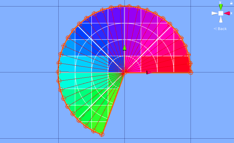
Draw small spheres at vertex positions to see whether your vertices are calculated correctly. If you still cannot get your mesh to work, a useful debugging aid is to draw a small sphere at each vertex position. This can provide you with a clue of what is going on. If the spheres are in the correct spot, then you know the issue is with the triangulation. In many situations, you can reduce the number of triangles so that they can become tractable by hand. In the circle, we can reduce the triangles to 3, for example. This allows us to see where the problem lies. (You will typically not have to calculate much, since if you can find one that is wrong, that may be enough to spot the bug.)
Unity’s gizmos are perfect for this, although there are some subtle issues to keep in mind. You will need a copy of the vertices (to avoid calculating them each frame), but you don’t want to serialize them with the scene (especially for large meshes), which means they will not render if you close and open the scene again without calling UpdateMesh. This is probably OK as long as you don’t forget and get confused about why they are not rendering. In the code below, I use OnValidate to reset the cached vertices if necessary.
Use debug textures to help to diagnose UV bugs. When debugging UVs, it is useful to use special textures such as square or polar grids with coloring to help you figure out which parts of the image maps to which part of the mesh. I often try to find or make a texture that is specific to what I am trying to do. There are some nice ones here.
For 2D meshes, implement a re-usable standard UV generation function. For 2D meshes, it is common to use a standard UV scheme that maximizes the texture use, possible with some constraints such as preserving aspect ratio or mapping the origin to the center of the texture. An implementation is given inside the MeshBuilder class below.
Make sure random data is used consistently by your algorithms. When using random data to generate your mesh, make sure that all your methods use the same random data, and that they don’t each generate their own. For example, if vertices are randomly generated, the UVs should use the same data, otherwise, there will be distortions that can fool you into thinking the UV code is wrong.
Use a context menu to allow testing in the editor without having to run the game. If you implement your mesh builder as a component, add a method that is called from the context menu or inspector button that you can use to test the builder in the editor.
Use components for simple builders, and a static method library if you have many builders. If you only have one or two mesh builders in your project, then designing your builders as components is probably the easiest way to go. If you have more, especially if they share some logic, you may want to consider a library of static functions instead.
For curves, calculate the number of triangles based on some accuracy metric to ensure visual consistency. For example, in our sector code above we specify the number of triangles directly; but it would be better to use the metric trianglesPerRadian, and then calculate the number of triangles we need from the angle. This way, the curve of the sector will approximate a circular arc with the same fidelity regardless of the angle.
int triangleCount = Mathf.CeilToInt(angle * trianglesPerRadian);
Full Implementation
Mesh Builder
using System;
using System.Collections.Generic;
using System.Linq;
using UnityEngine;

[RequireComponent(typeof(MeshFilter))]
public class MeshBuilder: MonoBehaviour
{
	private readonly static Color DebugSphereColor = new Color(1, 0.25f, 0);

	[Header("Debug Options")]
	[SerializeField]
	private bool drawDebugSpheres = false;

	[SerializeField]
	private bool printDebugInfo = false;

	[SerializeField]
	private float debugSphereRadius = 0.1f;

	//Use property instead to ensure initialization
	private MeshFilter meshFilter;

	//We keep this as a variable so we can draw debug Info
	private List<Vector3> vertices;

	protected MeshFilter MeshFilter
	{
		get
		{
			if (meshFilter == null)
			{
				meshFilter = GetComponent<MeshFilter>();
				//cannot be null since MeshFilter is required.
			}

			return meshFilter;
		}
	}

	public void UpdateMesh()
	{
		DestroyOldMesh();
		Preprocess();

		var mesh = new Mesh();

		vertices = CalculateVertices();

		DebugLog("vertices", vertices.Count);
		mesh.SetVertices(vertices);

		var triangles = CalculateTriangles();

		DebugLog("triangles", triangles.Count);
		mesh.SetTriangles(triangles, 0);

		var uvs = CalculateUvs(vertices);

		if (uvs == null)
		{
			//can be null if subclass does not support texturing
			DebugLog("uvs", null);
		}
		else
		{
			DebugLog("uvs", uvs.Count);
			mesh.SetUVs(0, uvs);
		}

		var normals = CalculateNormals();

		if (normals == null)
		{
			//can be null if subclass does override default normals
			DebugLog("normals", null);
			mesh.RecalculateNormals();
		}
		else
		{
			DebugLog("normals", normals.Count);
			mesh.SetNormals(normals);
		}

		mesh.RecalculateBounds();
		meshFilter.sharedMesh = mesh;
	}

	public void OnDrawGizmos()
	{
		if (!drawDebugSpheres) return;

		if (vertices == null) return; //can happen if no mesh was ever created.

		Gizmos.color = DebugSphereColor;

		foreach(var vertex in vertices)
		{
			var spherePosition = transform.TransformPoint(vertex);
			float radius = transform.lossyScale.magnitude * debugSphereRadius;

			Gizmos.DrawWireSphere(spherePosition, radius);
		}
	}

	virtual protected List<Vector3> CalculateVertices()
	{
		return new List<Vector3>
		{
			new Vector3(-1, -1, 0),
			new Vector3(1, -1, 0),
			new Vector3(1, 1, 0),
			new Vector3(-1, 1, 0),
		};
	}

	virtual protected List<Vector2> CalculateUvs(List<Vector3> vertices)
	{
		return GetStandardUvs(vertices, true, true);
	}

	virtual protected void Preprocess() { }

	virtual protected List<int> CalculateTriangles()
	{
		return new List<int>
		{
			0, 3, 1,
			1, 3, 2
		};
	}

	virtual protected List<Vector3> CalculateNormals()
	{
		return null;
	}

	[ContextMenu("Update Mesh")]
	protected void UpdateMeshTest()
	{
		UpdateMesh();
	}

	private void DestroyOldMesh()
	{
		if (MeshFilter.sharedMesh != null)
		{
			if (Application.isPlaying)
			{
				Destroy(MeshFilter.sharedMesh); //prevents memory leak
			}
			else
			{
				DestroyImmediate(MeshFilter.sharedMesh);
			}
		}
	}

	//Assumes a set of vertices in the XY plane
	protected List<Vector2> GetStandardUvs(
		List<Vector3> vertices,
		bool preserveAspectRatio,
		bool mapOriginToCenter
	)
	{
		var boundingBox = GetBoundingBoxXY(vertices, mapOriginToCenter);
		var map = GetStandardUvMap(boundingBox, preserveAspectRatio, mapOriginToCenter);

		return vertices.Select(map).ToList();
	}

	private Rect GetBoundingBoxXY(List<Vector3> vertices, bool mapOriginToCenter)
	{
		var anchor = vertices[0];
		var extent = vertices[0];

		foreach (var vertex in vertices.Skip(1))
		{
			if (vertex.x < anchor.x)
			{
				anchor.x = vertex.x;
			}

			else if (vertex.x > extent.x)
			{
				extent.x = vertex.x;
			}

			if (vertex.y < anchor.y)
			{
				anchor.y = vertex.y;
			}

			else if (vertex.y > extent.y)
			{
				extent.y = vertex.y;
			}
		}

		if (mapOriginToCenter)
		{
			anchor.x = Mathf.Min(anchor.x, -extent.x);
			anchor.y = Mathf.Min(anchor.y, -extent.y);

			extent.x = Mathf.Max(extent.x, -anchor.x);
			extent.y = Mathf.Max(extent.y, -anchor.y);
		}

		var size = extent - anchor;

		return new Rect(anchor, size);

	}

	private Func<Vector3, Vector2> GetStandardUvMap(
		Rect boundingBox,
		bool preserveAspectRatio,
		bool mapOriginToCenter)
	{
		Vector2 anchor = boundingBox.position;
		Vector2 size = boundingBox.size;

		if (preserveAspectRatio)
		{
			if(size.x < size.y)
			{
				size = new Vector3(size.y, size.y, 0);
			}
			else
			{
				size = new Vector3(size.x, size.x, 0);
			}
		}

		if (mapOriginToCenter)
		{
			return v => new Vector2(v.x / size.x + 0.5f, v.y / size.y + 0.5f);
		}
		else
		{
			return v => new Vector2((v.x - anchor.x) / size.x, (v.y - anchor.y) / size.y);
		}
	}

	private void DebugLog(string label, object message)
	{
		if (!printDebugInfo) return;

		if (message == null)
		{
			DebugLog(label, "null");
		}
		else
		{
			Debug.Log(label + ": " + message, this);
		}
	}

	private void GetVerticesFromMesh()
	{
		if (MeshFilter.sharedMesh != null)
		{
			vertices = MeshFilter.sharedMesh.vertices.ToList();

			DebugLog("vertices", "refreshed from mesh");
		}
	}

	private void OnValidate()
	{
		if(vertices == null)
		{
			GetVerticesFromMesh();
		}
	}
}
Circular Sector Mesh Builder
using UnityEngine;
using System.Collections.Generic;

public class CircularSectorMeshBuilder : MeshBuilder
{
	[Header("Mesh Options")]
	[Min(0)]
	[SerializeField]
	private int trianglesPerRad = 5;

	[SerializeField]
	[Range(0f, 360f)]
	private float angleInDegrees = 270f;

	override protected List<Vector3> CalculateVertices()
	{
		var triangleCount = GetTriangleCount();
		float sectorAngle = Mathf.Deg2Rad * angleInDegrees;

		var vertices = new List<Vector3>();

		vertices.Add(Vector2.zero);

		for (int i = 0; i < triangleCount + 1; i++)
		{
			float theta = i / (float)triangleCount * sectorAngle;
			var vertex = new Vector3(Mathf.Cos(theta), Mathf.Sin(theta), 0);
			vertices.Add(vertex);
		}

		return vertices;
	}

	override protected List<int> CalculateTriangles()
	{
		var triangleCount = GetTriangleCount();
		var triangles = new List<int>();

		for (int i = 0; i < triangleCount; i++)
		{
			triangles.Add(0);
			triangles.Add(i + 2);
			triangles.Add(i + 1);
		}

		return triangles;
	}

	private int GetTriangleCount()
	{
		return Mathf.CeilToInt(2 * Mathf.PI * trianglesPerRad);
	}
}
Circle Mesh Builder
using System.Collections.Generic;
using UnityEngine;

public class CircleMeshBuilder : MeshBuilder
{
	[Header("Mesh Options")]
	[SerializeField]
	[Min(0)]
	private int trianglesPerRad = 5;

	override protected List<Vector3> CalculateVertices()
	{
		var triangleCount = GetTriangleCount();
		var vertices = new List<Vector3>();

		vertices.Add(Vector2.zero);

		for (int i = 0; i < triangleCount; i++)
		{
			float theta = i / (float)triangleCount * 2 * Mathf.PI;
			var vertex = new Vector3(Mathf.Cos(theta), Mathf.Sin(theta), 0);
			vertices.Add(vertex);
		}

		return vertices;
	}

	override protected List<int> CalculateTriangles()
	{
		var triangleCount = GetTriangleCount();
		var triangles = new List<int>();

		for (int i = 0; i < triangleCount; i++)
		{
			int index0 = 0;
			int index1 = i + 1;
			int index2 = i + 2;

			if(i == triangleCount - 1)
			{
				index2 = 1; //second vertex of last triangle is vertex1
			}

			triangles.Add(index0);
			triangles.Add(index2);
			triangles.Add(index1);
		}

		return triangles;
	}

	private int GetTriangleCount()
	{
		return Mathf.CeilToInt(2 * Mathf.PI * trianglesPerRad);
	}
}

