(Original Image by everyone’s idle.)
This post was a originally published on Luma Labs, now dead.
As old as stimulus-response techniques are, they still form an important part of many AI systems, even if it is a thin layer underneath a sophisticated decision, planning, or learning system. In this tutorial I give some advice to their design and implementation, mostly out of experience gained from implementing the AI for some racing games.
A stimulus response agent (or a reactive agent) is an agent that takes inputs from its world through sensors, and then takes action based on those inputs through actuators. Between the stimulus and response, there is a processing unit that can be arbitrarily complex. An example of such an agent is one that controls a vehicle in a racing game: the agent “looks” at the road and nearby vehicles, and then decides how much to turn and break.
This definition is so broad that it is hard to think of agents that are not stimulus response agents. Some agents base their actions not on inputs, but on their internal state alone. See for example how random steering algorithms can lead to interesting behaviour.
Some agents don’t act. They just digest. The only way they can be useful if we look at what they are “thinking”. In fact, they are often designed with the sole purpose of “telling” us what they think, and they are not usually called agents, but rather decision systems. A face recognition system is an example of this. Of course, if we consider “telling” or “deciding” an action, these decision system become stimulus response agents too – but since we do not think of them as agents, the distinction is useful.
Design
1. Do not design your system around an overly simplistic view
The typical presentation of a stimulus response agent looks like this:

This presentation, while technically correct, is suitable only for flowers blowing in the wind. A real-world stimulus-response agent might look more like this:

Note that there are five factors that influence decisions:
- Game state is the mode of the game. For example, when an agent can be in a PLAY state (actively competing against the player) or a CHILL state (after taking over from the player at the end of the game.
- Global world state is the current conditions of the world, such as the weather or time of day.
- Local world state is what is normally thought of as the “stimulus”. It is the properties of the world around the agent that changes as the agents moves or otherwise acts in the world. For example, the shape of the path near a path following agent is part of the local world state.
- Agent parameters constitute the fixed limits of the agent’s sensory processing, and reactionary systems. For example, how far can the AI see, how quickly will it react, and how high can it jump. These parameters often describe the bounds for a state variable.
- Agent state is the changing parameters of the agent’s behaviour.
Note that all these can be mapped to the simplistic view of our agent. However, it is important to recognise the differences in these groups of variables, because the agent is made aware of them (connected to them) in different ways.
The world state is not sensed, but communicated through passed parameters, or a query to the world state object.
The game state is enforced by the game system, and typically the agent does not query or sense the game state – it is communicated from the outside.
The local world state is sensed by the agent through its sensors. Typically this means the agent must have hooks into the world. This data can be noisy or incomplete, so the agent might use filtering, and hence will store its own processed copy of the data.
The agent parameters are partially hard-coded, and partially generated on construction, or read from a file. These do not change over the agent’s life time.
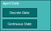
The agent state is calculated on updates. It has two parts:
- The discrete state is usually implemented as a state machine. In a vehicle driving agent, the discrete states can be PULL_AWAY, NORMAL, WRONG_WAY, and so on.
- The continuous state of an agent is the state determined by a set of parameters. For a vehicle driving agent, these can include “deviation_from_path”, “distance_from_closest_player”, “aggressiveness” and so on. Note that the continuous state for every discrete state can be described by a different set of parameters, possibly overlapping.In general, a different set of response equations will be used for every discrete state. In fact, the sole purpose of the state machine is to select the correct set of response equations for every situation.
The table below summarises the factors that influence a stimulus response agent’s decisions.
| Factor | Source |
| Game state | Game system |
| Global world state | World |
| Local world state | Sensors |
| Physical parameters | Hard-coded / File / Generated |
| Agent state | Calculated |
|
State machine transitions Equations |
2. Clearly distinguish between objects that have state, and those that do not (or should not)
It is easy to build objects that have states when they should not. It is, for example, reasonable to design a path-following object so that it keeps track of an agent’s progress along the path (such as the last node reached), to simplify communication between the agent and the path. In this scenario, the communication looks like this:
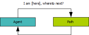
There are at least two problems with this set-up:
- every agent must have its own copy of the path; and
- the agent can’t ask any path information that violates the path object’s assumption about where the agent is.
To illustrate the last point, consider the situation where the path keeps track of the last node reached by the agent, and updates that node as the agent reports its position to the path object. It uses this node and the next node to interpolate a suitable position for the agent to move to. All is fine, until the agent needs information about the future, for example, it’s projection one second from now on the path. One second from now, the agent may have reached another node, something this simple system cannot handle properly.
Another way to do this, is for the agent to store the last node reached and pass it along its position in queries:
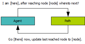
This does not solve the problem really – must the agent now store a separate node for queries into the future?
The best solution is to have a path manager. It has two responsibilities:
- to store any agent state information relating to the path – the last node reached, in our example; and
- to handle calculations for queries (based only on data from the path).

Now, when the agent asks the path manager about its projection 1 second from now, the path manager can check against the path whether a node will be reached, and perform the correct calculation. [In practise, the agent will transform time into distance travelled in time at its current velocity, so that the path manager only needs to know about distance, not time].
Every agent must have its own path manager, but the path managers can share the same path.
Consider another, slightly different, example. A certain agent has a “angriness” factor, which is randomised every 10 updates between two fixed extremes. Every type of agent has a different set of extremes (a monster will have higher extremes than a cow, for example), which helps determine the agent’s “personality”. It is easy to dump the extremes and the current value in one object (typically, the agent object). This is a poor design for two reasons:
- There is unnecessary duplicated data, with the associated disadvantages (such as making network packets bulkier, making save files of the game state bigger, and so on).
- The distinction between of agent state and agent parameters gets muddy. This makes it easier to make mistakes, overcomplicate the design, and introduce unnecessary inefficiencies.
A better design is to put the extremes into an “angriness profile” object, which can be shared by agents of the same type; in the example there will be two instances, one for cows and one for monsters.
Note that this issue goes hand-in-hand with preferring composition over inheritance hierarchies.
3. Draw pictures to show the ideal response to a given stimulus situation
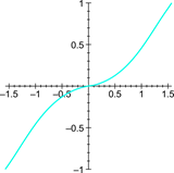
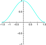
It is very important to define clearly what you want the agent to do given some stimulus. The following graphs shows a few examples for a vehicle steering agent.
 |
 |
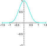 |
| Steering as a function of angular deviation from path. | Nitrous usage as a function of angular deviation from path (reckless driver). | Nitrous usage as a function of angular deviation from path (conservative driver). |
Most variables will depend on more than one other variable. Do not worry too much about that when drawing these diagrams. Focus on typical cases, and jot down any requirements or assumptions.
Also, do not try to write down any equations for your graphs. Any relationship can always be represented by a response curve, something that is much quicker to set up and easy to implement. A response curve is essentially a look-up table with linear interpolation. It can be used to approximate arbitrary functions by specifying the input range, and a number of output samples. The idea is discussed more thoroughly in AI Programming Wisdom 1 (The beauty of Response Curves by Bob Alexander).
4. Draw System Diagrams to show how variables relate
In a complicated system, it is easy to lose track of how variables relate. A forgotten relationship can often lead to behaviour that is hard to understand. Having an easy-to-reference diagram will be a great help in debugging faulty behaviour.
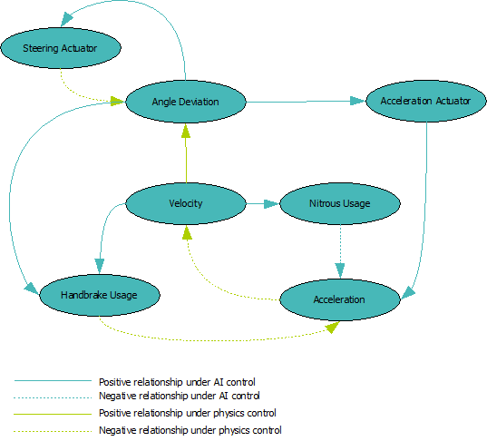
The diagram above distinguishes between relationships under AI control, and relationships that are under physics control – i.e. Relationships that cannot be changed by the agent. The diagram also indicates whether a relationship is positive (i.e. more of the one will result in more of the other), or negative (i.e. more of one will result in less of the other).
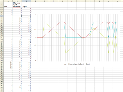
5. Use a spreadsheet to graph response curves to typical situations
Once you have your equations, you have to make sure that they actually describe the curves you intend. Also, in complicated formulas, it is important to check how these curves behave on typical data sets – especially if you employ filtering (see below).
6. Eliminate unimportant feedback loops.
Feedback is important for proper control in most systems. However, every loop makes it more difficult to analyse and understand the system – something that becomes apparent when things go wrong. If your system is complex, try to remove some of the loops (by removing some of the dependencies). You can always complicate your system once you have it working.
7. Prototype your agent on a computer algebra system
A computer algebra system (CAS) is the perfect environment to prototype a stimulus response agent:
- The high-level syntax, dynamic variables, and fat libraries allows you develop designs quickly, so that you can try out more designs.
- The built-in graph plotting capabilities are useful for debugging (see below) and understanding complex designs.
- You can simulate scenarios that are hard to obtain in the actual game, leading to a design that is much more robust.
Filtering
8. Filtering input, output, and intermediate values can drastically improve behaviour
There are several reasons to use filtering in your agent:
- To reduce noise that might confuse your agent about the state the world (or it) is in.
- To smooth out (and hence fill in) incomplete data. For example, a path made of line segments can be “filtered” so that it appears smooth to the agent.
- To make the actions of the agent seem more determined. An agent that changes it’s mind 10 times a second is not very believable.
- To prevent abrupt reactions to changes in the world that will make the agent less believable.
There are several approaches to filtering. One approach that works well in many cases is to change a variable only by some maximum amount, like this:
updateFilteredX(x)
{
   filteredX += clamp(x – filteredX, -maxIncX, maxIncX);
}
Here maxIncX is much smaller than typical values of x (using a tenth is a good starting point).
When you have many filtered variables, it becomes unmanageable to filter them all in this way – for every variable you want to filter, you need three extra variables, and you need to remember to use the right updating technique whenever the variable changes. It is better to encapsulate the filtering in a special class (as has been done in the Special Numbers Library – see http://code.google.com/p/specialnumbers/).
Other approaches to filtering include:
- statistical filtering techniques, such as least squares and Kalman filtering;
- convolutional filters; and
- PID controllers.
9. Make your filtering technique frame-rate independent, and do it from the start
The rate of updates of filters can have a dramatic effect on resulting behaviour. This rate can either fluctuate naturally (as it goes with frame rate), or be the difference between a Debug and Release versions of your application.
The resulting changes in behaviour makes it hard to:
- debug faulty behaviour; and
- spot problems to begin with (because it always works fine on your machine!).
How you make your filtering frame-rate independent depends on the method of filtering used. For the system explained above, it merely means updating with an amount proportional to the elapsed time (between updates).
updateFilteredX(x, elapsedTime)
{
   filteredX += clamp(x – filteredX,
                -maxIncX*elapsedTime, maxIncX*elapsedTime);
}
The updateFilteredX function above will use a smaller value for maxIncX than the one that does not compensate for time. It is for this reason that you should implement frame-rate independence from the start. Otherwise you will need to re-tweak all your values increment values again.
10. Do not filter the channels of n-dimensional data separately
If you filter a position, for example, by the method described above, you might be tempted to do something like the following:
updateFilteredXYZ(point)
{
   filteredPoint.x += clamp(point.x – filteredPoint.x,
                               -maxInc, maxInc);
   filteredPoint.y += clamp(point.y – filteredPoint.y,
                               -maxInc, maxInc);
   filteredPoint.z += clamp(point.z – filteredPoint.z,
                               -maxInc, maxInc);
}
The above code will lead to strange behaviour. Consider for example,
- filteredPoint = (0, 0, 0),
- point = (2, 1, 0) (for the next 4 updates)
- maxInc = 0.5
The variable filteredPoint will now go through these values on the next four updates:
(0.5, 0.5, 0)
(1.0, 1.0, 0)
(1.5, 1.0, 0)
(2.0, 1.0, 0)
If this filteredPoint represents an agent trying to reach (2, 1, 0). Notice that the points do not lie in a straight line, the agent will first move to point (1, 1, 0), and then turn before moving further. An onlooker will not understand this strange behaviour.
The correct way to implement filtering for multi-dimensional data is to add a clamped amount of difference between the value and the filteredValue to the filtered value.
updateFilteredXYZ(point)
{
   updateAmount = clamp((filteredPoint – point).len(),
                        0, maxInc)
   filteredPoint += (point – filteredPoint) * updateAmount;
}
Now the next four values of filteredPoint lie in a straight line:
(0.316, 0.632, 0)
(0.632, 1.265, 0)
(0.948, 1.897, 0)
(1, 2, 0)
11. Beware of filtering that reduces the range of a variable
Some kinds of filtering can reduce the range of a variable – for example, instead of reaching zero, a variable may merely come close to zero. This is important in checks that assumes variables will come to a have certain value eventually – these checks must be modified to compensate for the range discrepancies.
12. Beware of accumulated latency when filtering variables through various layers of logic
Filtering usually results in some latency. Where filtering is used in a layered system, these latencies can add up, and produce a system that is slow to respond. In many situations these latencies can be reduced or eliminated if you can make accurate predictions about the future.
You can reduce the filtering by using it only where it is really important – not everywhere. You can also exchange smoothness for a quicker response. How you accomplish this depends on the method of filtering you use; in the filtering described above you can increase the value of the increment.
If you feel adventurous, you can try out a system that filters only after it becomes aware that it is necessary. For example, the amount of filtering you apply can depend on the amount of noise measured over the last number of frames. In many situations you can approximate the amount of noise by the amount energy of the measured signal. Systems like these can be hard to make robust without resorting to difficult mathematics or special software.
You can also switch to a more sophisticated filtering approach, such as a Kalman filter or PID controller. PID controllers uses prediction to reduce latency; Kalman filtering uses a system model that makes it more effective in complicated scenarios.
13. Be Careful When filtering combined signals
You might want to add (or combine otherwise) several signals, filter this combination, and work on this filtered combined signal. This is a mistake when the signals have typical data transitions at different frequencies: one signal’s noise is another’s data.
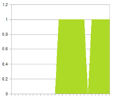
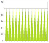
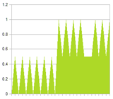
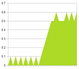
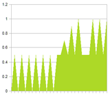
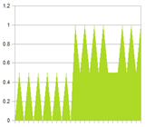
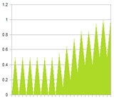
To illustrate the problem, look at the two signals below. Signal 1 is a low frequency signal, with a spike of noise. Signal 2 is a pure high frequency signal. The noise is clearly visible in the combined signal. Also shown are several filtered versions of the combined signal. Notice that the more we filter, the more we reduce the high frequency signal. And if we do not filter enough, the noise is still very present.
The solution is to filter the signals separately – the low frequency signal can be filtered much more than the high frequency signal – and only then combine the filtered sequences. The result is shown in the last figure.
 |
 |
 |
| Signal 1 | Signal 2 | Combined signal |
 |
 |
 |
| Combined signal filtered (0.1) | Combined signal filtered (0.5) | Combined signal filtered (1.0) |
 |
||
| Signals filtered before combined. |
14. Avoid if-then logic in response calculations.
If-then logic signifies one of two things:
- a state difference that should be implemented as proper discrete state of the state machine; or
- the need for a step function.
In the first case, your state should be broken up into two states, with proper transitions. A stimulus response agent is complex enough with you having to track trough various conditions to understand behaviour. Every state should have one response that depends continuously on the stimulus. Because state machines scale so badly, introducing more states is not very desirable either. There are of course several ways to organise states properly to alleviate the scaling problem, but this is the topic of another tutorial.
If your if-then logic is against the value of a variable (for example ‘if x > 0’), you can replace it with an appropriately chosen step function. Using step functions instead of if-then logic simplifies the design, and can be replaced with drop-in “smooth” versions when it becomes evident that it is necessary.
Testing and Debugging
15. Rendering the current state-machine state on screen.
It is a small point, but often strange behaviour results not from incorrect response to stimulus, but from incorrect state transitions. When implementing your agent inside the game, having state transitions visible on screen will make that kind of bug that much easier to spot.
16. Graph variables and their internal states on screen.
Graphing variables (filtered and unfiltered) over time on screen will save you hours of debugging time. Whenever your agent does something funny, you can see at a glance if there are variables with unexpected values that could explain the agent’s actions, perhaps using the CAS prototype as a reference.
Unfortunately, this tip becomes less useful as the system gets more complex. Having twenty plots on your screen will do little to spot problems.
17. Use unit tests to ensure correct implementation of formulas.
Stimulus response agents are perfect candidates for unit testing, especially when using the CAS prototype as a reference implementation. Unit testing your assumptions about the system will ensure correctness, and will help to make you aware of changes that break the system early. It will also make it easier to change and optimise formulas, or change them with smoother or sharper versions. Having a constant reference against which you can tweak parameters also allows you to be daring and make aggressive changes.
18. Use generators to mock the agent’s environment.
A generator is a object that generates a sequence of values. Typically it has a getValue() method, which returns a different value every time it is called. Generators are very similar to iterators, except that they usually generate values on the fly, rather than pointing to members of a container (although reading values from a container is one valid way to generate values). Generators are often used to implement iterators.
To implement unit tests and a CAS prototype, you need to mock various aspects of the game, the game world, and other agents. Using generators for this purpose makes mocking unbelievably easy and quick. Use generators to generate streams of
- elapsed times;
- path angle deviations;
- positions and velocities of other agents; and
- state transitions.
You can even mock parts of your agent to test sections in isolation. It helps if you build a library of generators and functions (response curves) that can be stacked together. You will do good to implement at least the following functions:
- step, line, and ramp;
- clamped line and sigmoid (or atan);
- cos, square, and saw tooth;
- exponential and exponential decay;
You should implement the following generators:
- a general generator that generates values from a function;
- a constant generator;
- a sum and product generator (generates the sum or product of two generators); and
- generators that generate random values of various distributions.
Conclusion
A complex stimulus response agent can be a challenge to design and implement properly; every approach has its set of headaches, and every solution brings other considerations to the table. Solving problems is just half the fun – not solving them is the other half!
